EP1001 Final project
Ideation
During one of my holidays, i got to witness a dispute due to a false start when i was working as a drone spotter over at science centre. Due to the lack of evidence, the organisers had to give the benefit of doubt to this participant despite 3 other people witnessing this happen. This could have been prevented if there was some sort of monitoring system to see if the go signal has been sent.
Inspirations:
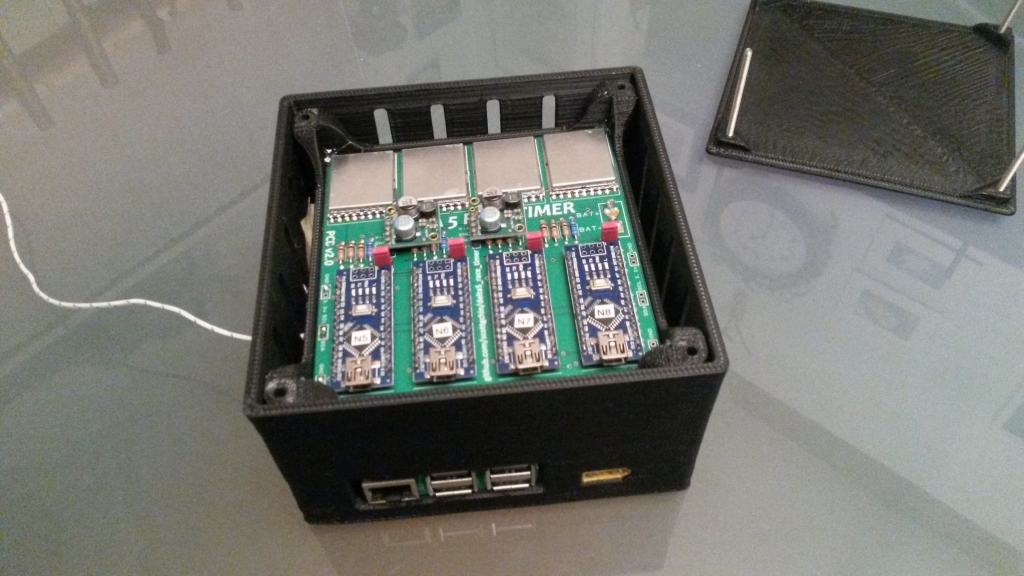
Rotorhazard race timing system:
Design goals:
- Firstly, the stand must be able to countdown to zero (3,2,1,Go), preferably audibly as well.
- Secondly, the stand must also be able to determine, within a few milliseconds, if the drone has lifted off prematurely and warn the user.
- Thirdly, the start button must be easily accessable by the user while minimising close contact with propellers for safety reasons.

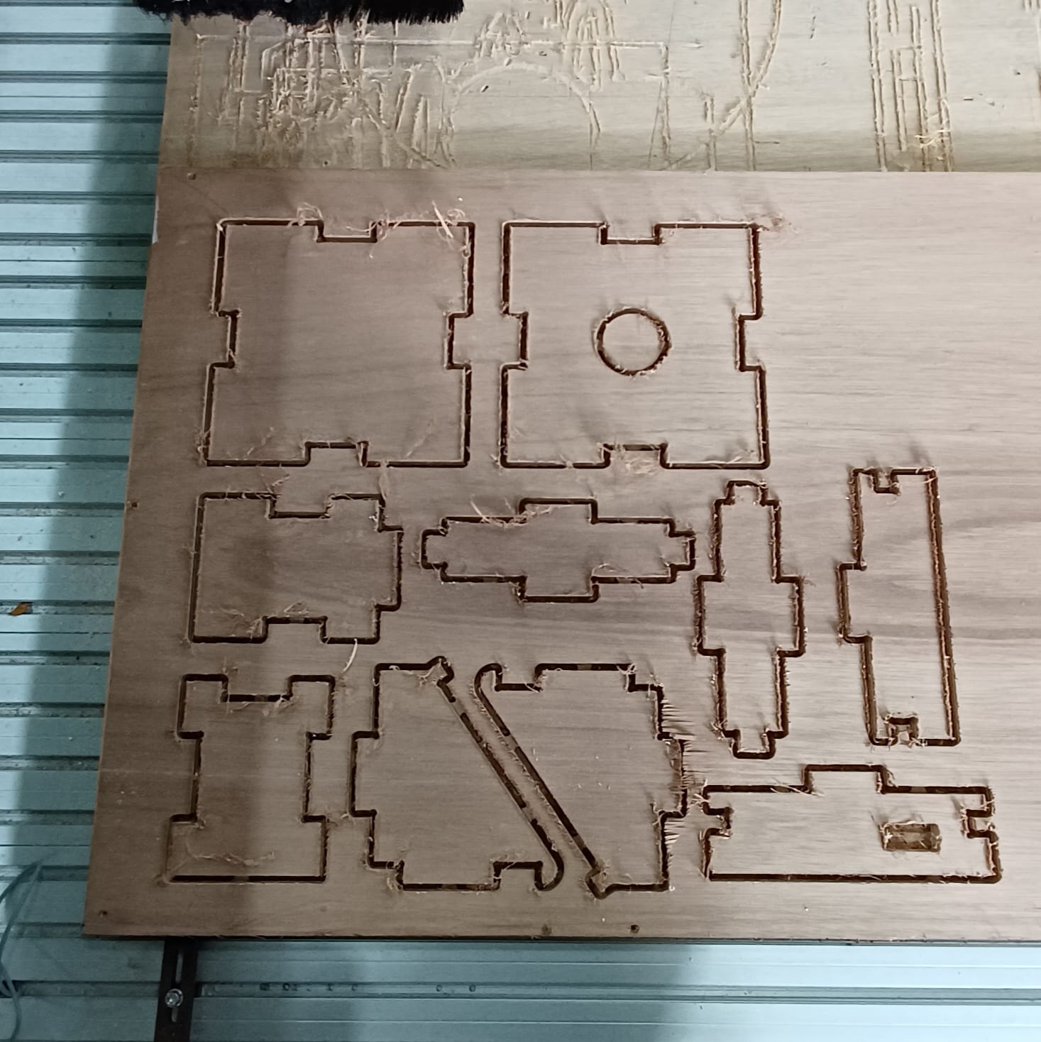
Unfortunately, I didn't take pictures of removing the tabs and sanding the pieces as my classmates were all busy at that time. Anyways, after doing these, I did a test fit, which confirmed that my racer does fit.
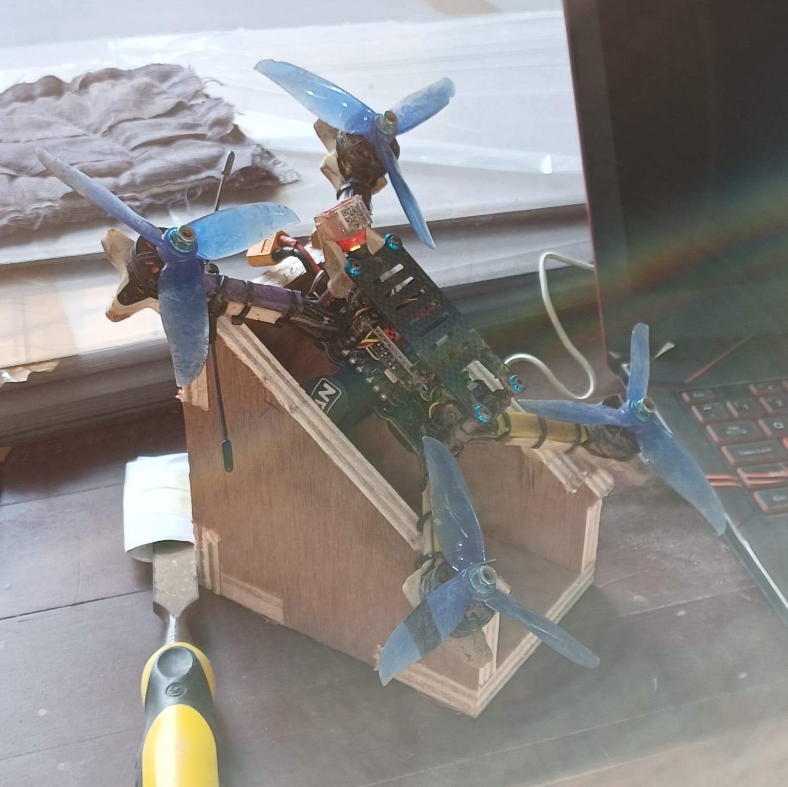
However, after doing another test fit at home with the battery attached, I found out that the batteries interfere with the stand. Therefore, I chose to use another drone for the rest of my test fitting.
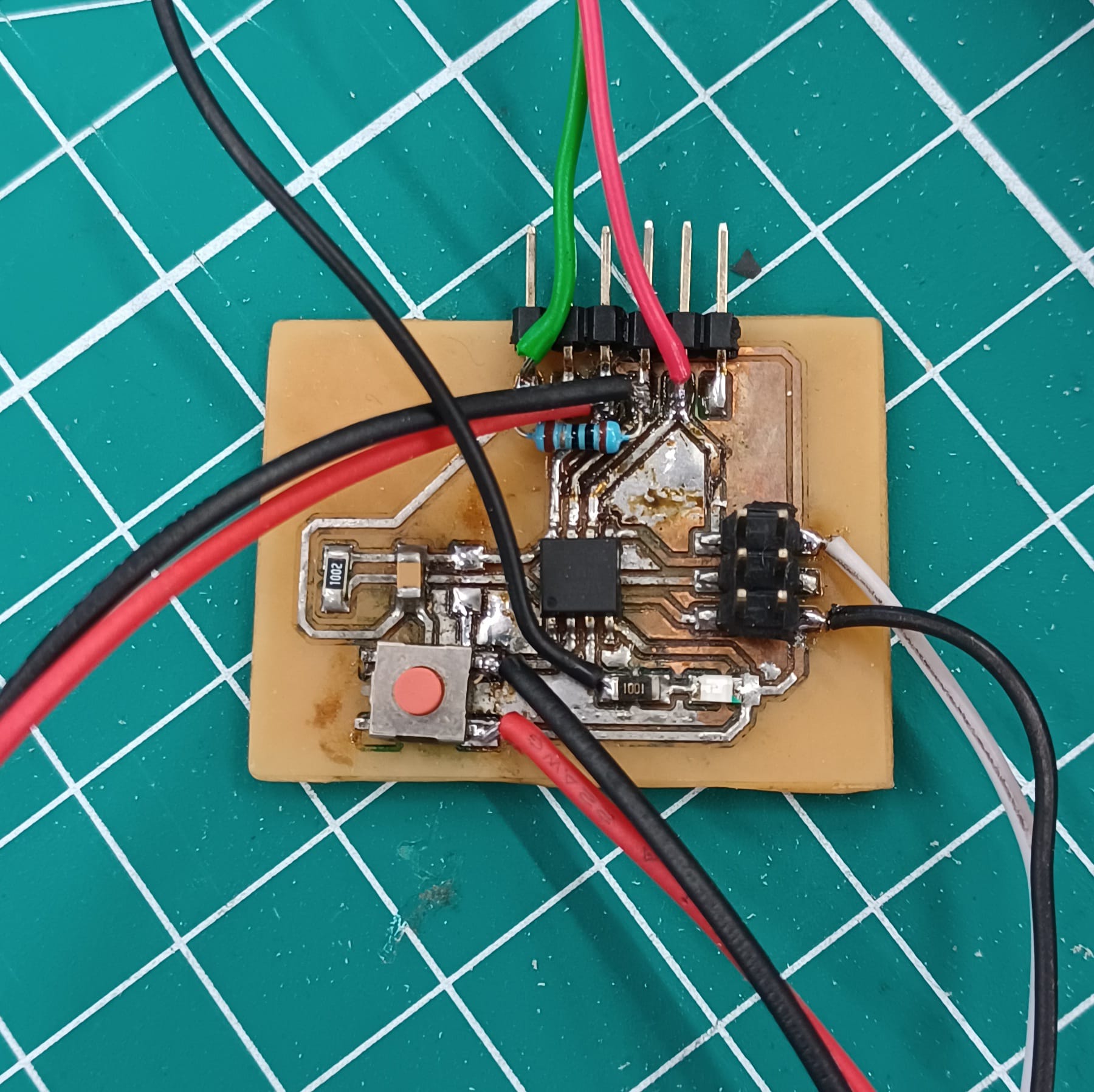
After I printed the switch mount and buzzer/LED indicator mount, I wired those up to the attiny board for further testing.
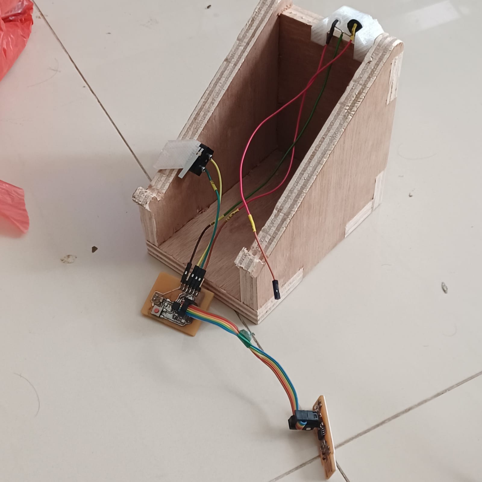
I chose to wire the buzzer and LED seperately to avoid sounding the error signal repeatedly, which can be quite irritating during a race if triggered.
After adjusting the switch to the proper location, I was able to get the switch to trigger when the drone is seated on the stand.
As I potentially need to sense an event during a countdown, i need to make use of interrupts in order to ensure that the takeoff is sensed reliably every time. Otherwise, if statements may miss the moment where the drone lifts off while being busy processing a delay.
Taking a look at online guides, the only external interrupt that is available to the attiny85 is int0 (pin 2), so I attached an interrupt named blink to pin 2, with a falling edge trigger, meaning that the ISR will trigger when the drone lifts off the sense switch.
#define LEDPIN 4
#define SWPIN 3
#define INTPIN 2
#define BUZZPIN 1

volatile boolean flag = false;

boolean takeoffallowed = false, launch = false;

void setup()
{
pinMode(LEDPIN,OUTPUT);
pinMode(BUZZPIN,OUTPUT);
pinMode(SWPIN,INPUT_PULLUP);
pinMode(INTPIN,INPUT_PULLUP);
attachInterrupt(digitalPinToInterrupt(FALLING), blink, LOW);
}
Below: Error LED shown when drone does a false start.
#define LEDPIN 4
#define SWPIN 3
#define INTPIN 2
#define BUZZPIN 1

volatile boolean flag = false;

boolean takeoffallowed = false, launch = false;

void setup()
{
  pinMode(LEDPIN,OUTPUT);
  pinMode(BUZZPIN,OUTPUT);
  pinMode(SWPIN,INPUT_PULLUP);
  pinMode(INTPIN,INPUT_PULLUP);
  attachInterrupt(digitalPinToInterrupt(FALLING), blink, LOW);
}

void loop()
{
  if(digitalRead(SWPIN)==0)
  {
    launch = true;
    digitalWrite(LEDPIN,1);
    digitalWrite(BUZZPIN,1);
    delay(500);
    digitalWrite(LEDPIN,0);
    digitalWrite(BUZZPIN,0);
    delay(500);

    digitalWrite(LEDPIN,1);
    digitalWrite(BUZZPIN,1);
    delay(500);
    digitalWrite(LEDPIN,0);
    digitalWrite(BUZZPIN,0);
    delay(500);

    digitalWrite(LEDPIN,1);
    digitalWrite(BUZZPIN,1);
    delay(500);
    digitalWrite(LEDPIN,0);
    digitalWrite(BUZZPIN,0);
    delay(500);

    digitalWrite(LEDPIN,1);
    digitalWrite(BUZZPIN,1);
    delay(1000);
    digitalWrite(LEDPIN,0);
    digitalWrite(BUZZPIN,0);
    takeoffallowed = true;
  }

  if(takeoffallowed == false && launch == true)
  {
    digitalWrite(LEDPIN,1);
    digitalWrite(BUZZPIN,1);
    delay(100);
    digitalWrite(LEDPIN,0);
    digitalWrite(BUZZPIN,0);
    delay(100);

    digitalWrite(LEDPIN,1);
    digitalWrite(BUZZPIN,1);
    delay(100);
    digitalWrite(LEDPIN,0);
    digitalWrite(BUZZPIN,0);
    delay(1000);
  }
  else if (takeoffallowed == true && launch == true)
  {
    digitalWrite(LEDPIN,1);
    delay(100);
    digitalWrite(LEDPIN,0);
    delay(100);

    digitalWrite(LEDPIN,1);
    delay(100);
    digitalWrite(LEDPIN,0);
    delay(100);

    digitalWrite(LEDPIN,1);
    delay(100);
    digitalWrite(LEDPIN,0);
    delay(100);

    while(1);
  }
}

void blink()
{
  takeoffallowed = false;
}
However, I realised during vigourous troubleshooting that i didn't actually need to use interrupts. So, i made the attiny check if the switch is pressed after the countdown was complete.
This is the result:
#define LEDPIN 4
#define SWPIN 3
#define INTPIN 2
#define BUZZPIN 1

volatile boolean flag = false;

void setup()
{
  pinMode(LEDPIN,OUTPUT);
  pinMode(BUZZPIN,OUTPUT);
  pinMode(SWPIN,INPUT_PULLUP);
  pinMode(INTPIN,INPUT);

  tone(BUZZPIN, 400, 500);
  delay(100);
  tone(BUZZPIN, 600, 500);
  delay(100);
  tone(BUZZPIN, 800, 500);
  delay(100);
  tone(BUZZPIN, 10000, 500);

}

void loop()
{
  if(digitalRead(SWPIN)==0)
  {
    digitalWrite(LEDPIN,1);
    digitalWrite(BUZZPIN,1);
    delay(500);
    digitalWrite(LEDPIN,0);
    digitalWrite(BUZZPIN,0);
    delay(500);

    digitalWrite(LEDPIN,1);
    digitalWrite(BUZZPIN,1);
    delay(500);
    digitalWrite(LEDPIN,0);
    digitalWrite(BUZZPIN,0);
    delay(500);

    digitalWrite(LEDPIN,1);
    digitalWrite(BUZZPIN,1);
    delay(500);
    digitalWrite(LEDPIN,0);
    digitalWrite(BUZZPIN,0);
    delay(500);

    digitalWrite(LEDPIN,1);
    digitalWrite(BUZZPIN,1);
    delay(1000);
    digitalWrite(LEDPIN,0);
    digitalWrite(BUZZPIN,0);

    if(digitalRead(INTPIN)==0)
    {
      digitalWrite(LEDPIN,1);
      delay(100);
      digitalWrite(LEDPIN,0);
      delay(100);

      digitalWrite(LEDPIN,1);
      delay(100);
      digitalWrite(LEDPIN,0);
      delay(100);
    }

    else
    {
      while(1)
      {
        digitalWrite(LEDPIN,1);
        delay(100);
        digitalWrite(LEDPIN,0);
        delay(100);

        digitalWrite(LEDPIN,1);
        delay(100);
        digitalWrite(LEDPIN,0);
        delay(100);
      }
    }
  }


}
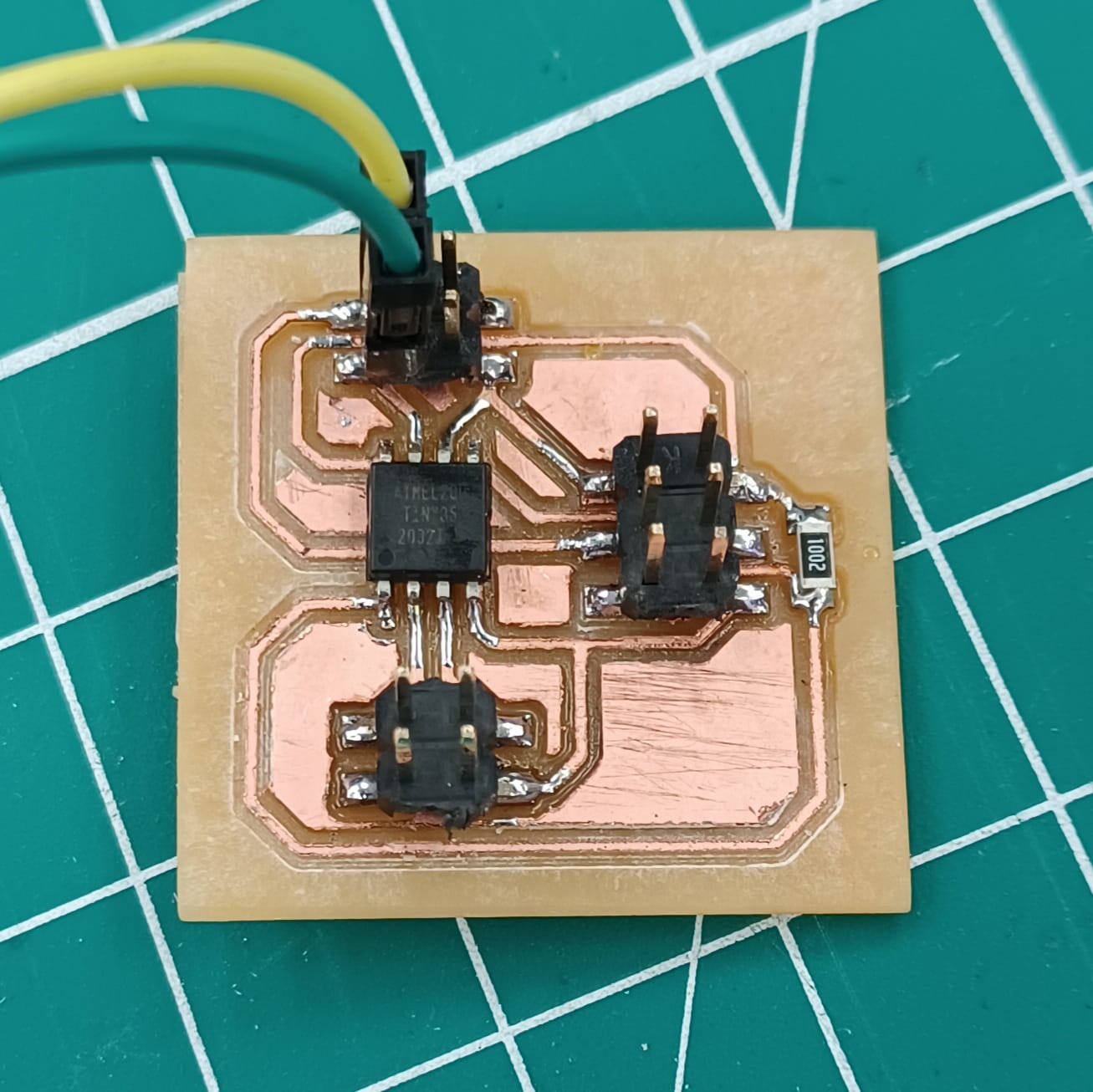
This, in combination with the new simplified board i milled, made the project more reliable as it used vertical pin headers that were less prone to fatigeing the wires.
For the v2 board, i got rid of the built in button and led, breaking out all 4 io pins i need (led, buzzer, sensesw and startsw)

Milling v2 board gif:
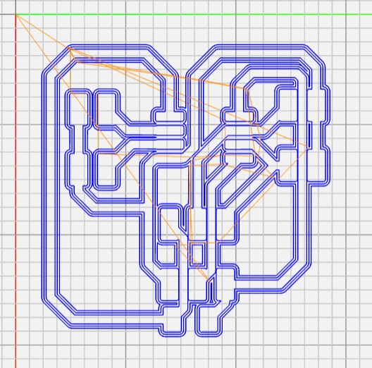

A quick comparison between the v1 and v2 board.
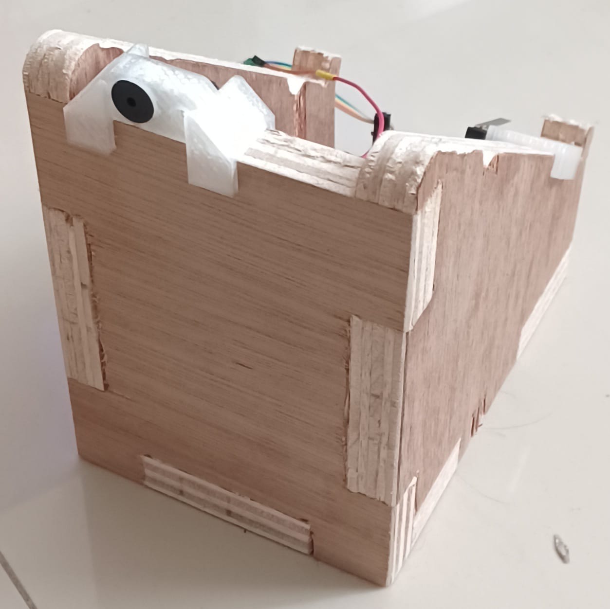
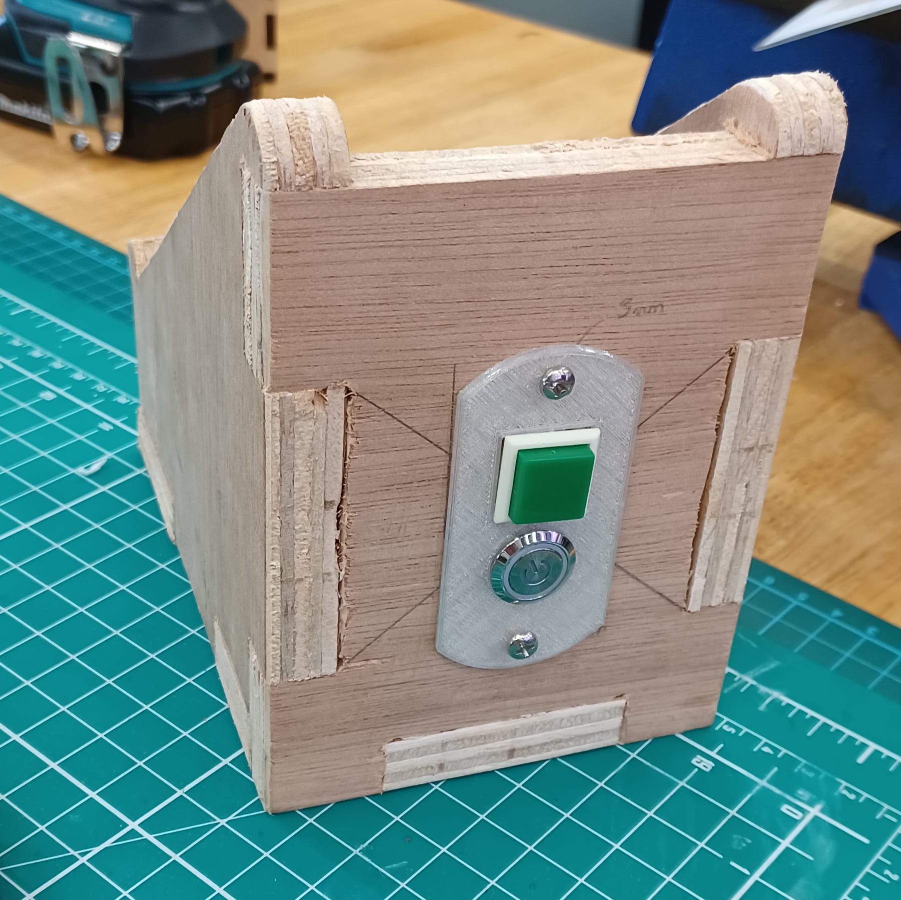
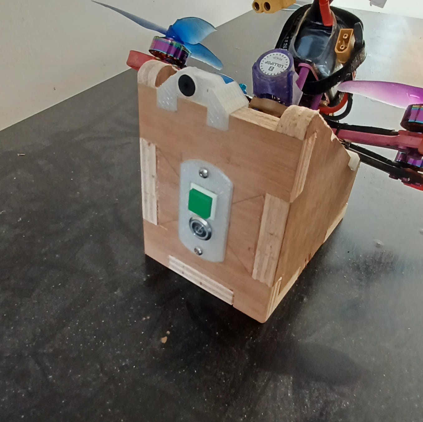
During the session, i also knocked out a hole in the back to mount this switch panel.
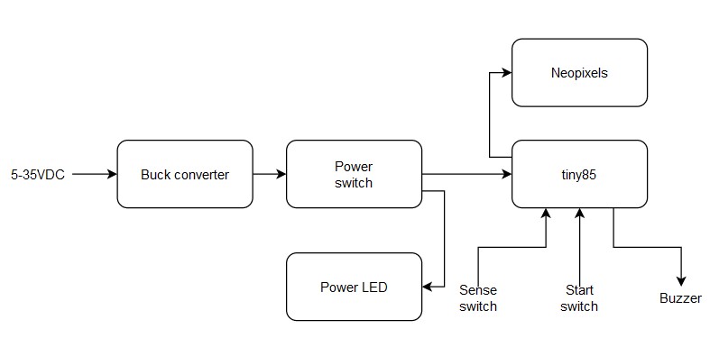
I decided to rewire the indicator led on the back to neopixel leds to the front to make it more asthetically pleasing.
Since the individual addressable leds only need 1 output pin, i can simply swap out the wiring. Furthermore, i still had 3/4 of flash memory left on the tiny85, so that won't be a problem.
Turns out if i only power a few leds at a time, i would not need a high current supply, and i can use the 5v rail coming from an uno for my initial tests. So that was what i did.
After trimming the strip to 9 leds and rewiring the strip to the v2 pcb, i mounted it to the front, hoping that the fpv camera on the drone would be able to pick up some glare.
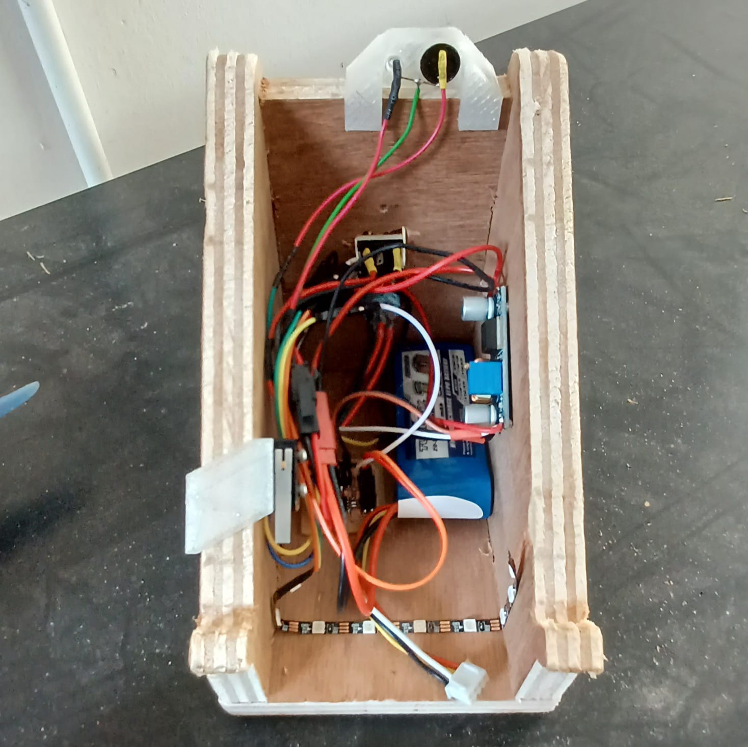
I also added an LM2596 Switched mode buck converter for reliable power up to 35VDC, as most users of the project would have access to a 2 to 6 cell li-po with a JST connector.
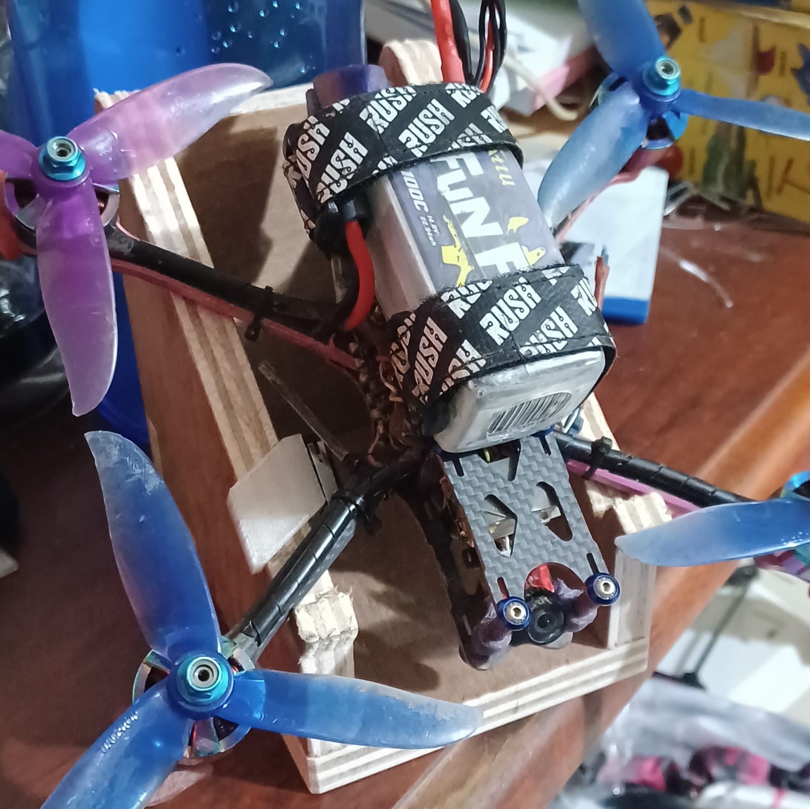
These are the heroshots for the project. I may add some printed covers for the wiring if time permits. I'm also thinking of printing some feet to allow the stand to be spiked down into grass.
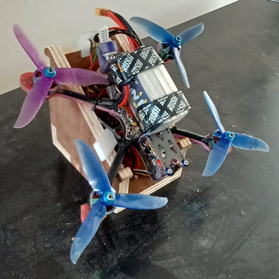
Final project video:
Due to ongoing NDP regulations, I am unable to conduct an actual drone test, so, this was the best demo i can safely and responsibly do as of now.
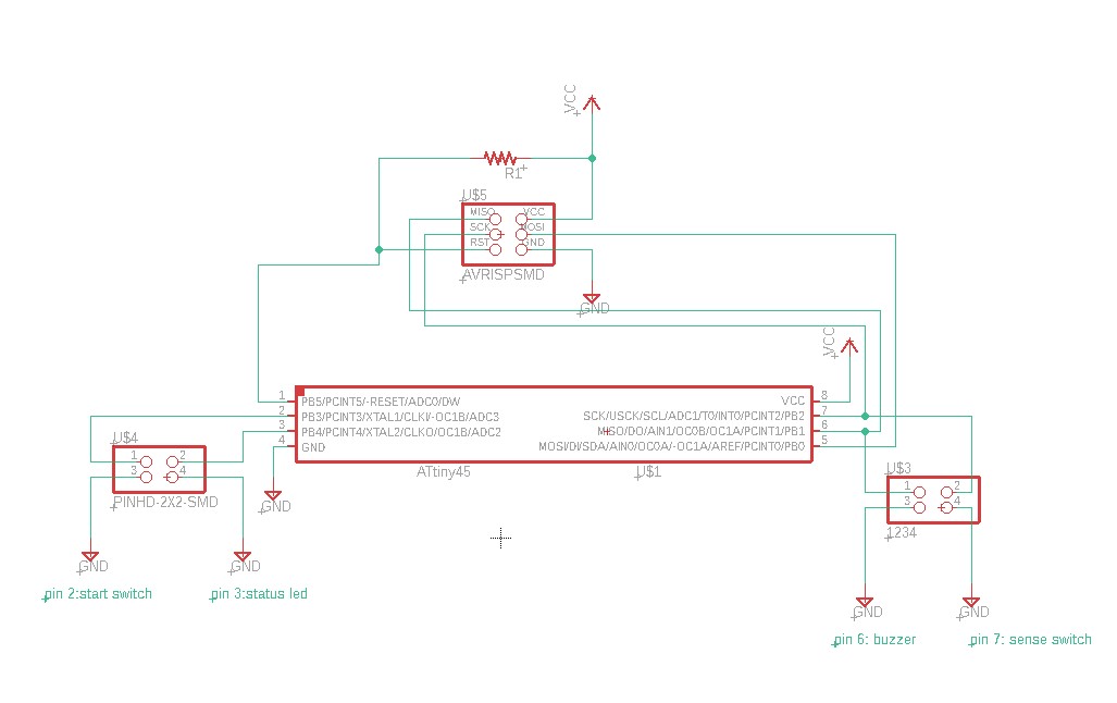
Hardware diagram:
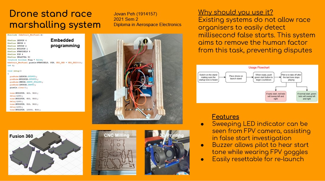
Project poster: